Compression-release brakes, exhaust brakes and retarders explained
Auxiliary braking systems slow a vehicle by making the powertrain absorb energy instead of relying only on friction at the wheel brakes. The mechanism matters: changing an engine's valve events, restricting exhaust flow and resisting a rotating shaft are different ways to achieve that result.
Cummins describes a compression-release engine brake as turning the engine into a power-absorbing air compressor. Its role is to assist vehicle retardation and reduce demand on the service brakes. Cummins / Jacobs, Compression Release Engine Brake
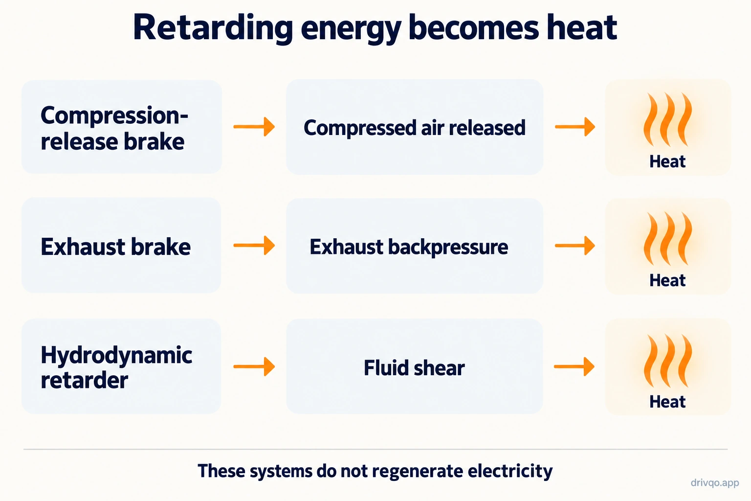
Functional energy paths, not a valve-timing or installation drawing. These examples dissipate energy rather than storing it in a traction battery.
Compression release: prevent the air from giving the work back
During compression, the moving vehicle drives the engine to squeeze air. If that compressed air simply expands again, it returns much of the compression work to the piston. A compression-release brake changes the sequence by opening the exhaust valves near the top of compression while the engine is not fuelling. The air escapes, so much less of that work comes back during expansion. Jacobs, Compression Release Brake, How it works, bulletin 6482469, 2023
This is why “compression” alone is not the complete explanation. The release event is central to the braking action. The system uses the engine's cylinders and a specialised valve-actuation arrangement; it is not the normal exhaust event merely occurring at its usual time.
Exhaust brake: make pushing the exhaust out harder
An exhaust brake raises exhaust backpressure. In the Jacobs exhaust-throttle example, a flap downstream of the turbo restricts flow, increasing the work done during the exhaust stroke. That differs from deliberately venting the cylinder at the top of compression. Cummins / Jacobs, Exhaust Brake, bulletin 6482465, How it works
The two approaches can be combined in a designed system. Their existence does not make them interchangeable retrofit parts, and the supplier's application guidance should not be replaced by a generic diagram.
Hydrodynamic retarder: turn shaft energy into heat
A hydrodynamic retarder uses fluid between a rotating rotor and a stationary stator. The rotor accelerates the fluid; the stator changes its motion. The resulting reaction resists shaft rotation, and the generated heat must be removed through the cooling arrangement. The published Voith explanation identifies fill level and rotational speed as factors in retarding torque. Voith / Driventic, Truck Retarder: structure and functioning
The rotor/stator terminology resembles other fluid devices, but the stator here is fixed and the purpose is braking. Our torque-converter article describes a different application of fluid momentum.
Electromagnetic retarder: resist motion through induced currents
Telma's design uses a stationary electromagnetic assembly and rotating conducting parts separated by an air gap. Induced eddy currents create a resisting torque and heat the rotors; ventilation rejects that heat to the surrounding air. No rubbing friction interface is required between stator and rotor for that braking action. Telma, Operating principle
This is not automatically regenerative braking. A system can use electromagnetism and still dissipate the vehicle's energy as heat. Regenerative braking instead attempts to recover some energy electrically for storage and later use.
Why a single power percentage is misleading
Retarding output depends on the system, engine or shaft speed, operating limits and cooling capacity. The sources here explain mechanisms; they do not validate a universal claim that engine braking extracts 90% of rated engine power. A proportion of braking events handled by an auxiliary brake is also not the same quantity as a proportion of engine power. Keep the measurement and its conditions attached to any number.
Illustration: AI-generated and checked against the explanation. Conceptual only; sources are linked beside the relevant claims.