How a torque converter works: fluid drive, torque multiplication and lock-up
A torque converter transfers engine power to a transmission through moving fluid. Its impeller drives the fluid, its turbine receives that flow, and its stator redirects returning fluid. A lock-up clutch can add a mechanical connection when operating conditions permit. The hydrodynamic converter and the transmission's ratio-changing gears perform different jobs. Honda, Hondamatic engineering history, ZF, Torque Converter
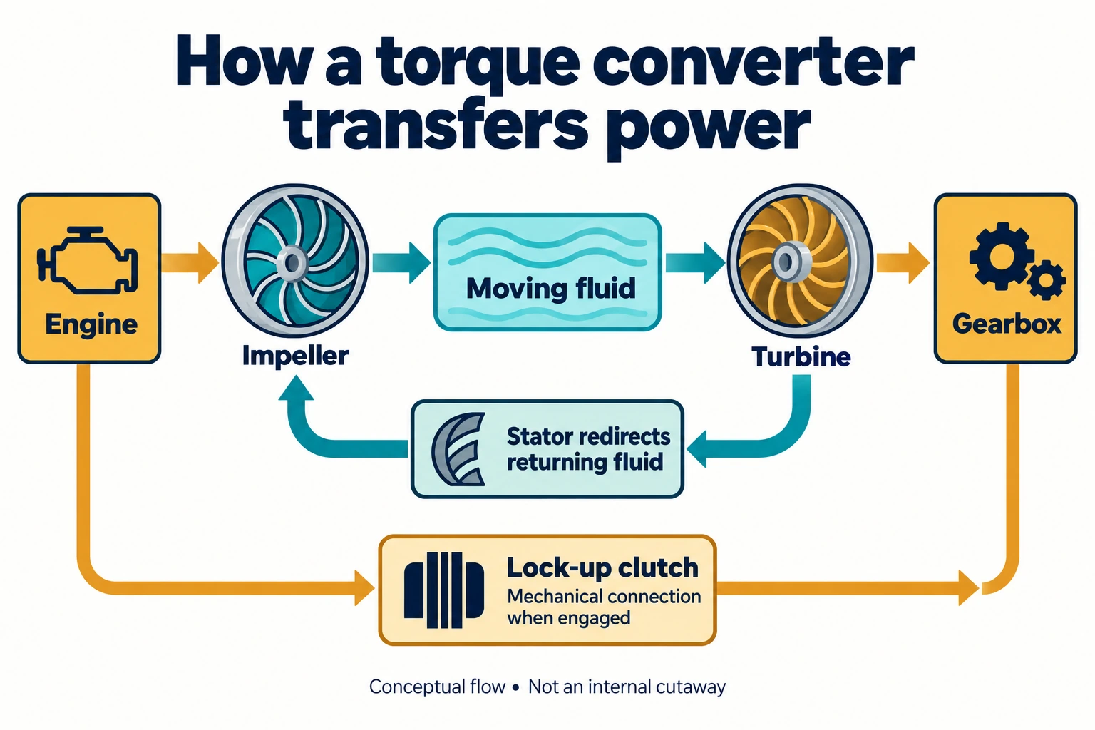
Functional flow, not the physical positions of components inside the converter.
Start with the fluid path
The impeller, also called the pump, is driven from the engine side. It accelerates oil toward the turbine. The turbine is connected to the transmission input, so the force exerted by that moving oil can turn the gearbox input.
The fluid then returns toward the impeller. Honda's historical account describes these three central members—pump, turbine and stator—and explains how its engineers used the stator's reaction force in the original Hondamatic's controls. That particular control system is historical; the basic fluid-transfer explanation is the relevant part here. Honda
What does the stator add?
At a large speed difference between impeller and turbine, the returning fluid benefits from redirection before it reaches the impeller again. The stator provides that reaction and enables torque multiplication.
In a conventional one-way-clutch stator arrangement, the stator is held against rotation in one direction during multiplication. As the turbine catches up and the fluid conditions change, it can freewheel. A useful educational description appears in Manuel Martinez's MIT course report. This is a teaching report, not a peer-reviewed production test. MIT, How a Torque Converter Works
Why extra torque is not extra power
Rotational power is torque multiplied by angular speed:
Power = torque × angular speed
The turbine can therefore receive more torque while turning more slowly than the impeller, without receiving more power than the engine supplies. Real fluid losses also turn some energy into heat. At stall, the turbine is stationary: it can experience torque, but its mechanical output power is zero because its speed is zero. This is an operating principle, not an instruction to perform a stall test. MIT course report, operating principles
This distinction also explains why a claimed torque-multiplication ratio needs an operating condition attached. It is not a fixed multiplier applied throughout the drive.
What the lock-up clutch changes
Fluid transmission is useful during launch, but slip is not desirable in every situation. A lock-up clutch creates a mechanical path between the engine-side converter housing and the transmission input side. The converter can then avoid relying entirely on hydrodynamic transfer.
Lock-up also creates a vibration-management problem because a more direct connection transmits engine torsional fluctuations. ZF describes torsional dampers as part of its converter designs and links improved damping to earlier lock-up operation. ZF, Torque Converter
It is therefore misleading to picture a modern converter as permanently “slipping until motorway speed.” Toyota's description of its Direct Shift eight- and ten-speed automatics identifies an expanded lock-up operating range as one of its efficiency measures. Exactly when a clutch engages or allows controlled slip depends on the particular system and calibration. Toyota, Direct Shift-8AT and Direct Shift-10AT
Is the converter the entire automatic gearbox?
No. The converter manages the engine-to-transmission connection; the gearbox provides the transmission ratios. Toyota's technical description discusses both its converter and its multi-speed gear arrangement because they are distinct parts of the drivetrain. Toyota
When comparing automatic transmissions, separate three things: the launch device, the ratio-changing mechanism and the control strategy. “Torque-converter automatic” is useful shorthand, but it does not tell you the shift calibration, ratio spread or real-world fuel consumption of a particular car.
For the wider comparison, see CVT vs DCT vs AMT.
Illustration: AI-generated and checked against the explanation. Conceptual only; sources are linked beside the relevant claims.